Nidac PAC1 Door Controller
The Presco™ door access control system has been designed to cater for users who want door access control without the headaches and expense of larger and more complicated systems.
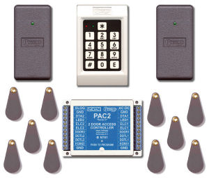
The Presco™ system is built around the PAC (Presco™ Access Controller) series of digital door access decoders which utilise the latest microprocessor technology to operate most electric door locking devices on the market. The decoder, together with a Presco™ encoder (Presco™ keypad models PRE & PSE, Presco™ PRX and SPRITE proximity readers) or other devices with the addition of a Presco™ Interface Module, model PIM, offers affordable access control to restricted areas for up to 400 users.
Features of the Presco™ PAC series decoders include:
- Two models of door access controller to choose from: the PAC1 single door controller & the PAC2 two door controller
- Compatible with the entire range of Presco™ encoders including the PRE standard keypad, PSE rugged keypad & PRX and SPRITE proximity readers
- Can be interfaced with other readers such as Wiegand format readers or Dallas iButton™ readers (CS Technologies CS-KEYRDR reader) with the addition of a Presco™ PIM interface module
- Split system for maximum security
- Door Forced Open detection
- Door Open Too Long (DOTL) function
- Request To Exit (RTE) function
- Automatic Door Relock function
- Easy on-site programming using a Presco™ keypad
- 400 client programmable user codes
- All programmed information is stored in non-volatile memory
- Up to 10 encoders can be connected to a single decoder
- Two heavy duty 5 Amp relay contacts for electric latch control
- Can operate fail safe and fail secure electric locking devices
- Two 1 Amp Normally Open DOTL alarm relay contacts
- 36 month manufacturers warranty
- Designed and manufactured in Australia
The programmable features descibed below can be set independently for each door.
Automatic Door Relock Function
When the DOOR input is used then the Automatic Door Relock function can be used. This feature turns the ELC relay off 1 second after the door is opened (not unlocked) when a momentary code or the EGRESS input has been used (no matter how long the time for the ELC relay operation has been set for). The purpose of this feature is to stop people following someone through the door by ensuring that the door locks once it closes.
Door Open Too Long (DOTL)
The DOTL timer is used to warn if the door has been held open for too long after a valid access (either via a code or EGRESS). When the door has been opened a count down timer is started. If the door has not closed again by the time this counter expires then the DOTL output will activate (pull down to GND) and will remain active until the door is closed. Note that if a value of 0 has been set for the DOTL time then the door is allowed to remain open indefinitely.
Door Forced Open
A door forced open condition is defined by the situation where the door has been opened but a code or EGRESS has not been used to gain access. When this condition occurs the DOTL output will activate (pull down to GND) and will remain active for 30 seconds or until the door is closed again, whichever is the longer time. The DFO feature must be disabled if a free (unmonitored) inside door handle is used instead of an EGRESS button. When this feature is disabled the DOTL timer will be started when the decoder detects that the door has been opened.
One Minute Lockout
To increase security the decoder can be set to lock out all codes for a period of 1 minute after 5 incorrect codes have been tried. This feature should not be enabled if access must be guaranteed in an emergency situation.
Use Two Codes
The decoder can be set up to operate in one of the four modes described below.
- One User Code Only - Any one of the programmed user codes will operate the ELC relay
- Any Two User Codes - Any two of the programmed user codes can be used together to operate the ELC relay
- Code 000 or 001 and any other user code - The user code stored in memory 000 or 001 used together with any other valid user code will operate the ELC relay
- Sequentially Numbered User Codes - Two user codes in sequential memory locations must be used together to operate the ELC relay. The pair of locations start with an even numbered memory, eg. 000 and 001, 056 and 057, 138 and 139, etc. not 001 and 002.